WCM-2000 Multi-Element Water Content System
General Description
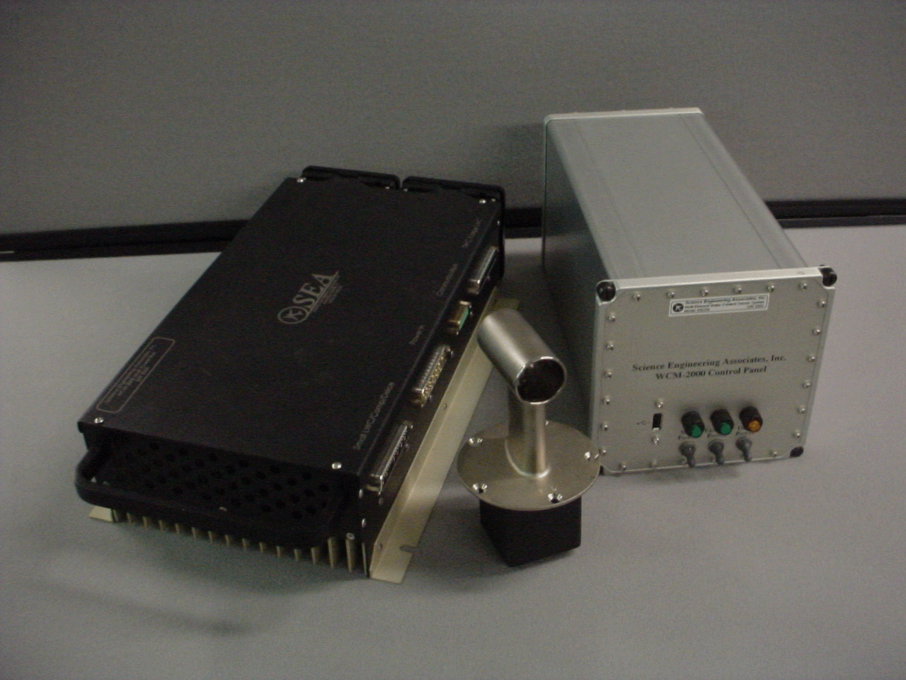
The SEA Model WCM-2000 Multi Element Water content System was designed to provide aircraft and wind tunnel users with a single, rugged sensor to simultaneously measure Liquid Water Content (LWC) and Total Water Content (TWC) and Ice Water Content (IWC). The instrument consists of four heated stainless steel elements each with a different shape or size. Each element is directly heated by low voltage DC current flowing through the element. These elements are maintained at a constant temperature, typically 140 °c, by a digital, closed loop, control system.
Given the dimensions of each element and the true airspeed of the airflow the power level set by the control system to maintain temperature can be converted directly into the water content of the air stream.
Three of the heated elements are exposed directly to the air stream and incoming cloud water. A fourth element, the reference/comp element, is arraigned to be exposed to the airflow but not to incoming cloud water. This element is used to establish the “dry power term” that is subtracted from the other three element’s power readings to establish the measured water content.
The instrument makes two independent measurements of LWC using two different diameter LWC elements. The small LWC element is the same diameter, 0.5 mm, as the classic JW/CT LWC sensor. The second element is the same size, 2 mm, as the CSIRO (King) LWC sensor.
Wind tunnel tests have shown that the two LWC elements have less than 1% false response to Ice Water Content (IWC) in the air stream. This compares favorably to wire wound LWC elements which typically have a false response to IWC of 10 to 20 %.
The instrument uses a scoop shaped sensor to collect and measure both liquid water (LWC) and ice crystals ( IWC). The combined total of LWC and IWC is referred to as Total Water Content (TWC). By subtracting the LWC measured by the LWC elements from the TWC measured by the scoop element, the IWC can be calculated.
The shape and size of the TWC sensor can be varied to match the TWC measurement to different ranges of airspeed, altitude, water content, etc. In addition to temperature control for the four heated elements, the deice system is also temperature controlled. During operation the deice power is adjusted to maintain the instrument housing at a constant 50 °c, which is comfortably warm to the touch. Maintaining the instrument housing at a constant temperature provides a stabilized thermal environment around the sensing elements which leads to improved LWC and TWC measurement accuracies.
Temperature control of the heated elements and the deice heaters allows the unit to be operated safely and continuously at zero airspeed.
The system consists of three major components, the sense head, the power box and the control unit (this can be embedded into the M300 system or a separate system). The sense head is mounted in the air stream. The power controller is mounted near the sense head. The control unit is mounted where it is convenient for the user.
Documentation
Control Box: Drawing P/N: 400220-MGlobal Connections: Schematic P/N: 400200-E
Major Components: Drawing P/N: 400200-M
Power Box: Drawing P/N: 400210-M
Power Box to Control Box Cable: Schematic P/N: 400240-E Drawing P/N: 400240-M
Power Box to Sense Head Cable: Schematic P/N: 400230-E Drawing P/N: 400230-M
Power Cable: Schematic P/N: 400250-E
Sense Head: Drawing P/N: 400201-M
WCM EPROM Table Version Update Instructions
Software Changes
User's Guide
Upgrading a WCM Software
Download Latest WCM Software
If you would prefer to see this list in a non-interactive and less user-friendly plain-HTML format, you can do so here.
Applications
- Severe Weather Research.
- Cloud Physics Research.
- FAA Aircraft Icing Certification.
- High Altitude, High Speed Ice Crystal Content Measurement.
- Wind Tunnel Spray Measurement.
- Wind Tunnel Reference Instrument.
Features
- Direct Measurement of LWC and TWC.
- Derived Measurement of IWC.
- Rugged Sensor Designed for High Speed, High Altitude Operation.
- Safe Operation at Zero Airspeed (see endnote 1).
- 28 vdc Power Standard (AC Power Systems are also available).
- Light Weight.
- High Water Content Capability.
- Ethernet/Network Data Output, UDP/TCP, Serial.
- Easy Interface to Aircraft Flight Data Computers.
- Small Size (Control Unit can be combined with existing Data Systems).
- Measurement over a Wide MVD Range Including SLD drop sizes.
- Excellent Deice Performance.
- First Principles Instrument for LWC and IWC.
- Very Low Contamination, < 1%, of LWC Measurement by Ice Crystals.
- Aircraft Icing Severity Indicator.
- Detection and Measurements of Ice Crystals especially at High Altitudes and Airspeeds.
Specifications
LWC/TWC Range see endnote 2 |
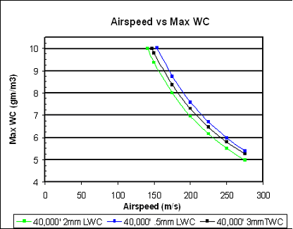
0-10 gm/m3, TAS < 150 m/s, SL - 45,000 ft 0-6 gm/m3, TAS < 230 m/s, SL - 45,000 ft |
Airspeed Range |
0–275 m/s, ( 0–533 kt) |
Measurement Range |
10–275 m/s, (20–533 kt), see endnote 1 |
Power Supply Range |
18–32 vdc, 28 vdc nominal |
Power Consumption see endnote 3 |
3.5 amp minimum 11 amp typical 54 amp maximum |
Sensor Head Dimensions |
3.25 “ x 1.2 “ x 2.25” external 5.65 “ x 3.25 “ x 3.25” overall |
Power Control Box Dimensions |
15.2” x 7.8” x 3.5” |
Sensor Head Weight |
1.5 lb |
Power Control Box Weight |
12.0 lb |
Data Output |
Ethernet Network TCP/UDP |
Data Rate |
1-10 Hz, selectable |
1 - “Safe Operation” means that the instrument can be left fully powered on continuously at zero airspeed without damage. However as the airspeed is reduced to zero, the effective sample volume decreases to zero and the measurement of LWC is not possible. Depending on the specifics, some minimum airspeed is required to establish a minimum acceptable sample volume. Please contact SEA for details about measurements at very low speeds.
2 - Refer to graph for details. Maximum possible LWC/TWC varies slightly with altitude and is about 10% greater at sea level compared to 40,000 ft at the same airspeed.
3 - Power supply current varies with airspeed, altitude, ambient temperature and water content. Supply currents include deice power. Minimum current is for zero airspeed at 20 °c. Typical current is for 67 m/s, -9 °c, 1.5 gm/m3. Maximum current is for maximum possible LWC/TWC.
 SEA
SEA